Looking for a quick & easy to use piston vise---where canted valve pockets are no problem.
Here is a a story where I explained my ideas concerning my piston vise on Speedtalk.com
http://www.speedtalk.com/forum/viewtopic.php?t=999&view=next&sid=3471d36edcdf9a4a356920a96ffce908
contains the entire thread.
I looked at piston vises years ago when I was wanting one and I ended up building my own sort of like the ABS 3 jaw chuck type that has the extended jaws.
-ABS gets over a $1000 for their vise which is mounted on a tilt table and it grips the pistons in the oil ring grooves.
-----------------------------
-I didn't like the price (which is probably really wasn’t all that bad) and I didn't like the orientation of the 3 jaws
-They have one jaw parallel to the "Y" axis on the mill table and I could see NO reasonable explanation for that idea.
--------------------------------
-I decided that I could and would just build my own and save the $1000.
-So I made a tilt table and I mounted a 3 jaw chuck to it but I rotated the jaws so one jaw is parallel to the "X" axis on the mill.
-I wanted a way to get the wrist pin square to the "X" axis so I milled the inside of that one jaw extension so that I can push the wrist pin against it to get the piston squared quick and easy.
-----------------------------------
-To do the angled valve notches like a BBC I used an aluminum degreed VW crank pully, cut the center out of it to make the hole about 4.640", and installed 4 adjustable spring loaded balls inside of set screws inward from the outer circumference, so that I can slip this over the piston and snap onto the top ring groove.
-The pressure of the spring loaded balls is not a lot so it allows me to rotate the degree wheel easy.
-Then I have a swing away pointer that I roll up, and I adjust the degree wheel to zero while the piston is square to the "X" axis.
---------------------------------------
-I had to figure out the EXACT tilts and angles of the canted valve heads and I keep those on a reference chart.
-This means I do NOT have to change the tilt of the mill head so there is no set up required for the mill head and no re-set up to get the mill head back to square again.
-------------------------------
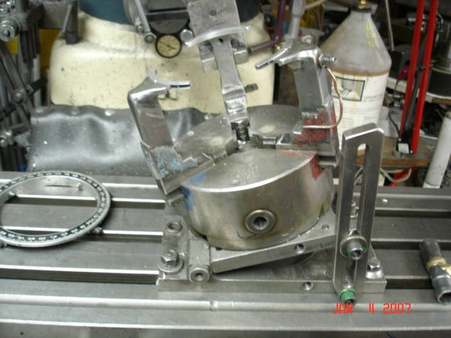
-The vises' tilt table is doweled to fit the T-slots and it bolts up with 4 T-slot bolts.
-I tilt the vise up on the right hand side whatever angle like 23 for conventional SBC's.
-I almost always do a center punch mark of the pistons like where I have a left and a right piston or I'll center punch just one if all the pistons are symmetrical.
-Then I use a centering tool in a end mill holder to get those punch marks centered on the mill.
---------------------------------
-The total time it takes me to flycut a set of canted or SBC left right pistons is about identical, maybe quicker to do the canted pistons because I only have to do two setups where the SBC's have 4 positions to set up.
-I doubt it would ever take me 80 minutes to do about any normal sort of flycut job on SBC'c or BBC's, more like about 40 to 50 minutes.
-------------------------------
-I made the extended jaws slightly different than ABS plus I machined several oil ring spacer inserts that spread the jaw clamping load over a wider area to reduce the stress and distortion to the pistons.
-These three pieces are shown setting on the jaws.
-
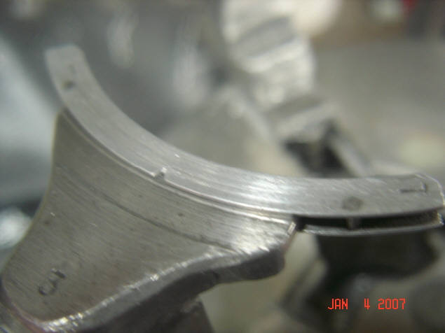
Here is a close up of the ring groove insert.
-Before I cut the machined ring into 4 pieces I marked the top----then I notched one side of each of the pieces so because I had ended up with several thousandths difference top to bottom when I machined the groove into the aluminum spacer.
-I also drilled each of the 3 sections and pressed in short small dowel pins to register to the pieces to the jaws----so the pieces would stay located and not slip off the jaws when you rotated the piston.
-Originally I machined the jaws to fit into 1/8” oil ring grooves-----but later on I remachined the jaws to some millimeter size like 3mm which is .118”---and then went thru the entire process of machining another aluminum ring to make new groove inserts.
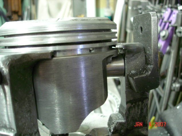
-This photo shows the wristpin pressed up against the inside of the machined “X” jaw.
-There isn’t any ring groove spacers installed so you can see the gap betwenthe ring groove and the jaws.
-I have also found that I can machine some pistons between the 2nd & oil ring grooves with a slight recess as shown here so that I can grip this groove rather than using the oil ring groove.
-The metal fixture attached to the “X” jaw is used when the piston happens to be inverted like when machining the inside of the underhead area for weight.
-I run a bolt thru the wristpin and thru the small hole to secure the pin and this positively keeps the piston from rotating and I don’t have to apply as much pressure to the jaws for clamping.
-A coupe of problems with this ring groove clamping idea is---when you have real high pin locations where the pin intrudes into the oil ring grooves----I have to use a donor wristpin and cut a notch out of the end so it will fit under the bottom of the “X” jaw as the full round pin end will interfere with the “X” jaw
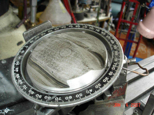
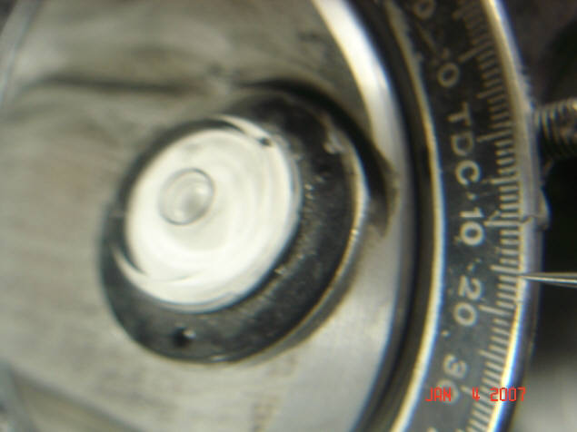
-here is the degree wheel assembled onto the piston---and the pointer which stays mounted on the jaw but swings down and out of the way when not being used.
-At this point the wrist pin has been squared up against the inside of the machined “X” jaw and the degree wheel & pointer are adjusted to zero.
-When the piston already has an existing notch it is pretty easy to just set a bubble in the valve notch and adjust the tilt table and the rotate the piston to get real close.
-The amount of rotation here is about 15.5

Bill's Piston Vise
Bill Jones' Photo Gallery Page 21