MISCELLANOUS FLOWBENCH MODIFICATIONS
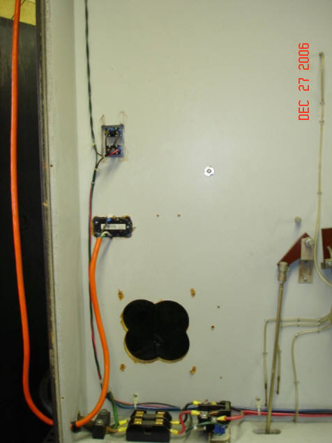
-Looking into the rear of the SF300 flow bench shows a cloverleaf pattern where I hole sawed 4 overlapping holes----to make an access hole in to the two fuses.
-When I first got my flow bench in 1980 I had issues with it blowing fuses--and it became a nuisance to pull the heavy flowbench out for the wall and to remove all the screws that held the large rear panel onto the back.
-This cloverleaf hole was made with a holesaw, easy to do and allowed enough room to get a hand in there to change the fuses.
-I covered the front with a simple piece of plastic.
------------------------------------------------------------------------------------------------------------------------------------------------------
-The orange cord is an addition---where I installed a 110volt duplex outlet so that I had a 110v plug on the face of the flowbench---for things like the battery charger for my digital barometer.
-This cord is wired so that the ground is an “isolated ground”---meaning it is grounded to it’s own metal ground rod.
-I had found that when welding aluminum (about 15feet away) and using high frequency----that bothered my digital barometer and scrambled the display until I isolated the ground.
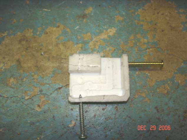
TEFLON CORNER FEET FOR BOTTOM OF FLOW BENCH CABINET
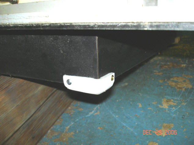
-Having to move the flow bench out from the wall is quite a chore as the wooden framework against the floor has a lot of surface friction.
-So to make the task of moving the flow bench in and out from the wall I made up a set of 4 teflon corner feet.
-Sort of crude machining shown here but the idea works excellent.
-The screws are long enough that they go clear across the machined section----which is where the wood is----and into the teflon on the other side---for a fairly secure installation.
-This shows the flow bench cabinet tilted and propped up for installation of one of the four teflon feet.
-There are two knobs on the front of the SF300 flow bench that control either the air flow in or the airflow out of the bench during flow testing---by moving the large round disk down and this opens the large airway hole.
-The knobs have threaded ends that screw into the brass plate that is bolted to the underside up inside the lower plenums of the flow bench.
-The threads inside of the brass piece have a tendency to wear out---and I have replaced both brass pieces several times in 26 years.
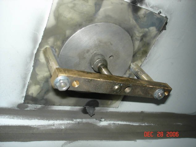
-Normally there is only three holes---but I finally got smart and made the plate with 2 sets of 3 holes so that I basically had a spare set of new threads by removing the brass bar and moving it sideways to the left to use the new set of holes.
-To tell if the threads are worn---open either valve on the front panel at least a half inch---then firmly push down and then pull back up----if the knob moved up and down that shows you how loose the brass plate threads are to the shaft threads.
-This backlash slows down the flow testing process---especially if you are trying to adjust up or down in small increments--as you have to rotate the knob maybe a full turn or more to reverse the action of the air valve plate.
-This photo is up inside the flowbench---looking at the intake.
-As the knob is opened to increase air flow the large washerlike disk moves downward and opens a large hole for the air to flow.
-The bottom of the stem that is in the center of the washer disk is a steel 3/8NC thread and the brass piece is also threaded and mounted rigid---so the threads of the stem screw the stem downwards and over time wear on the brass threads---which is better than to have the steel stem threads wear out and require replacement of that shaft.

SuperFlow 300 Modifications
Bill Jones' Photo Gallery Page 17